Building a basic codeplug for DMR (DMR Part 2)
What is a "codeplug"?
Confusingly, a codeplug is neither code, nor a plug! The term originates from a time when a physical plug was used to configure a radio's parameters. Nowadays it refers to a configuration file, which is typically prepared on an external PC and then uploaded to the radio.
Overview
This blog post continues from Part 1, and it assumes that you already have:
- A callsign
- A DMR ID
- A DMR rig - I will be using a Retevis RT3S for this example
- The programming software and cable for your rig. For the RT3S, the Windows software can be found here: RT3S Software
The example described below assumes that you are within reach of a DMR repeater on the Phoenix network, and that you know the details of that repeater (transmit and receive frequencies, color code).
For now will configure the rig to access the DMR+ (Phoenix) network via a repeater. Subsequent posts will explain how to add analogue repeaters and simplex channels, hotspots, other networks, etc.
The steps involved are:
- Set up the basic parameters for the rig
- Configure "Digital Contacts" - which contain the talkgroup information
- Configure "Channel Information" - which defines the radio channels to be used and maps these to talkgroups
- Configure "Zone Information" - which maps the channels to a zone and thus makes them available on the rig
- Optionally, create and upload a "Contacts" list. This is simply a file containing a list of worldwide DMR IDs mapped to callsigns, names and locations. It isn't essential to have a Contacts list, but if present it enables the rig to display the relevant information.
1. Basic Parameters
Fire up the codeplug software (CPS RT3S), and the screen should look something like this:

The menu tree on the left of the screen selects the various configuration screens. Initially it will display "Basic Information", and there should be nothing that needs setting here.
Now go to General Setting:

These are the settings that work for me... and I must admit that I don't understand all of them yet!
These are the ones that need setting:
- Radio Name: Set this to your callsign
- Radio ID: Set this to your DMR ID
- Freq/Channel Mode: Set this to Channel for DMR mode (the other setting turns on VFO mode which might be more useful for selecting FM channels)
- Group Call Match and Private Call Match: Untick these for "promiscuous mode". Promiscuous Mode means that you will receive signals from all talkgroups, including ones that you haven’t explicitly programmed. Be careful when responding with this mode enabled, as you are quite likely be transmitting on a completely different talkgroup to the one you are hearing.
- Intro Screen: Set this to Char string and put some text in the boxes for a friendly greeting when you turn on the rig
- Mic Level: Set this too high and you'll annoy everyone! Use a parrot server (explained below) to compare your audio level with others and adjust it accordingly. 3 or 4 should be sufficient.
- Tx Mode: Set this to "Designed CH" (which should probably read "designated CH") so that you transmit on the talkgroup selected and displayed on your rig. The other settings ("Last Call CH", etc) will cause your rig to transmit on the talkgroup last heard... which is probably not what you intended especially if combined with promiscuous mode
2. Digital Contacts
Each and every talkgroup that you wish to use needs to be configured as a Digital Contact.
The full list of talkgroups for the Phoenix network can be found here: Talkgroups
I recommend configuring the following:
- 1 - Worldwide calling
- 2 - Europe
- 9 - Local
- 13 - Worldwide English calling
- 80 - UK chat
- 81 - UK chat
- 82 - UK chat
- 83 - UK chat
- 84 - UK chat
- 113 - Worldwide English
- 119 - Worldwide
- 123 - Woldwide English
- 129 - Worldwide
- 235 - UK Calling
- 801 - Southeast region (substitute your own region and/or add other regions)
- 23426 - Freestar
- 23526 - Hubnet
- 9990 - Echo test
Each Digital Contact is simply added to the table. Here is what it would look like after adding the first three talkgroups:
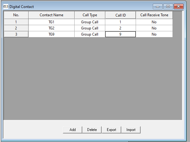
"Contact Name" is the reference that will be used when building the Channels later. It can be anything, but "TG1", etc, is recommended.
Always select Call Type as "Group Call".
Call ID is the talkgroup number.
3. Channel Information
Go to the Channel Information section, and there will probably be a single channel "Channel1", looking something like this:

Now we need to create a Channel for each of the talkgroups created earlier. The screen for the first channel, containing talkgroup 1, will look like this:

Important things to note are:
- Channel Mode: Digital. When this is selected, the Analog section becomes greyed-out.
- Scan List: I don't use scan lists for DMR. They are more useful for FM channels.
- TOT(s): This is your transmit timeout in seconds. Recommended 180 or 240.
- Power: Recommended High for repeater access.
- Channel Name: This is the name that will be displayed on your rig. It can be anything you like, within 16 characters. In my case I use the following naming convention: "Repeater Talkgroup Hint", hence "GF" for GB7GF, "T1" for Talkgroup 1, and "WW Call" for Worldwide calling
- RX and TX frequency: As appropriate for your repeater
- Admit Criteria: Color Code
- Contact Name: This is where you select the appropriate talkgroup from the list created in step 2.
- Color Code: Must be set according to your repeater
- Repeater Slot: Phoenix has a convention that national and international talkgroups are on slot 1, and regional and local talkgroups are on slot 2.
Now continue to add a channel for each of the talkgroups defined in step 2. There is a handy copy-and-paste method that saves some typing:
- Right-click "Channel Information" in the tree menu, and select Add. This creates a new, blank channel entry labelled "Channel1" (or you can press the "Add" button at the bottom of the previous channel entry)
- Right-click an existing Channel in the tree menu (e.g. "GF T1 WW Call"), and select Copy.
- Right-click the new "Channel1" entry, and select Paste.
The new Channel1 entry now contains a copy of the previous entry. Only the following fields now need to be checked and/or edited:
- Channel Name
- Contact Name
- Repeater Slot
Continue until there is a channel configured for every one of the talkgroups defined in section 2.
4. Zone Information
Zones are a useful way to have separate configurations for different situations, such as for different repeaters and different modes. In this example we are configuring one repeater, and so we will configure one zone containing all of the channels.
The RT3S effectively has two VFOs, A and B, displayed on the upper and middle lines of the display. When defining a Zone, channels need to be assigned to A or B. For the Phoenix network, I recommend assigning Slot 1 channels to A (the upper line), and Slot 2 channels to B (the middle line).
When first switching on the rig, or when changing zones, the RT3S will default to the first channel in the list. Therefore, place your most-used channel in the first position.
Here is the Zone Information screen (for the purposes of illustration it is an incomplete configuration with only a few channels defined):

The following edits are needed in the Zone Information screen:
- Set the name of the Zone, which will be displayed on the bottom line of the RT3S. The name of the repeater is a good choice: GB7GF in this example.
- Use the "Add" buttons to add channels to each of the two banks (A and B). I recommend setting 235 (UK calling) as the first entry in A, and 9 (Local) or your regional talkgroup as the first entry in B.
If following the convention of A=timeslot 1, then A will contain 235, 1, 2, 13, 80, 81, 82, 83, 84, 113, 119, 123, 129, 23426, 23526. B will contain 9, 801 (and any other regions), 9990.
5. Save, and Upload
Save the configuration file (File/Save As...), connect the rig via USB, and Program/Write Data.
If all goes well, the RT3S is now properly configured.
6. Contacts.CSV
The master copy of the DMR contacts list is held here: RadioID.net ...the same place that you already registered your ID.
Update (Jan 2022): RadioID.net now charges for downloads. However, a free download for Retevis is obtainable from the Ailunce website: https://www.ailunce.com/ResourceCenter#DigitalContacts
Unfortunately the RT3S only supports a maximum of 120,000 contacts, and the worldwide total is now approaching 200,000 entries. Therefore it is necessary to create a subset - usually by selecting the countries that you are most interested in.
The RadioID Generator enables you to select and deselect countries, to create and download a suitable file.
Alternatively, if you know what you are doing in Excel (or equivalent), download the complete database and manipulate it in Excel before saving in CSV format. Currently it is possible to keep below 120,000 contacts by removing Canada and USA and leaving the rest of the world in place.
The rig must be set to CSV mode. On the RT3S, do the following: Menu / Utilities / Radio Settings / ContactsCSV / Turn On
Now connect your rig to your PC with the USB cable, and in the CPS RT3S software do Program / Write Contacts.

In the screen that now appears, Import your local CSV file, then Write to the rig.
N.B. For some bizarre reason you must have a copy of Microsoft Excel on the PC when working with Contacts, otherwise the CPS software will give an unhelpful error message.
7. Testing
All set?
Whilst testing, it is a good idea to keep an eye on the Phoenix dashboard. Can you see your repeater in the list?
On the rig:
- Press the down arrow, so that the "D" (for digital") indicator is pointing at VFO B.
- Press the red key, so VFO A is disabled (indicated by a red loudspeaker icon).
- Use the channel-selector knob to find T9990.
- Key up, and say a few words.
The echo server should then repeat your transmission back to you. Also, you should see activity including your callsign and DMR ID on the Phoenix dashboard.
Success? Now it is time to go to talkgroup 235 and put out a call. Red key to re-enable VFO A, up arrow to select VFO A, and red key again to disable VFO B. Check that talkgroup 235 is being displayed, and good luck...
In the next article we will build a Hotspot and add it to the RT3S codeplug.


Comments
Post a Comment