1. What is a Hotspot?
Part 1 and Part 2 described how to get a DMR rig onto the Phoenix network using a local repeater. This assumes, of course, that you are in range of a suitable repeater! What if you are not? Or if you are visiting another location without coverage? The solution is to build your own mini-repeater, known as a Hotspot.
This blog assumes you have a DMR ID, and a working DMR rig. If not, please return to Part 1.
A Hotspot is a low-power multi-mode digital repeater. It has an internet connection (wireless or wired) that connects it to the various amateur radio networks. And it has a small UHF transceiver that makes it accessible as a repeater from a local DMR handheld.
Hotspots typically support more than one mode and network - so they can be used to connect to Phoenix, Brandmeister, FreeDMR, TGIF, DSTAR and more. There are several commercial Hotspots available, and a few variations of software. Hotspots can be simplex or duplex, supporting one or two timeslots on DMR. This blog post describes one (relatively) simple configuration:
- Hardware: Raspberry Pi Zero WH, with a simplex MMDVM Hat as the radio part.
- Software: Pi-Star
- DMR configuration: Phoenix. Other networks can be added later, and these will be the subject of future blog posts.
2. Hardware
2.1 Raspberry Pi
Any Raspberry Pi is fine, except that the basic Pi Zero (without a "W") is not recommended. The "W" model comes with WiFi, and the "WH" comes with the header (multi-pin connector) already fitted. You can of course buy a W, and solder the header yourself.
...or search eBay.
2.2 Radio module (MMDVM)
Search eBay for "MMDVM hotspot".
Look for one which comes with a single antenna (simplex).
Optionally, look for one which comes with a case.
Optionally they can come with an OLED display, which is fun to include but not necessary for the correct operation of the hotspot. Mine does not have a display.
Some come with the antenna connector already soldered onto the board, or you might need to solder it yourself. Make sure you solder it on the correct side of the board (see photo below), so that the antenna sticks upwards with the header connector downwards!
It will probably come with a spare set of header pins for the Pi, but you won't need these if you bought a Pi with the header already fitted.
2.3 Case
If your MMDVM module did not come with a case, these can be bought separately on eBay. Search for "MMDVM case".
2.4 Micro SD Card
You'll need a memory card for your Pi. Any good-quality Micro SD card is fine (e.g. from Amazon). 16 GByte is recommended, although mine seems perfectly happy with 2 GByte.
2.5 Power supply
The Pi needs powering, via one of its micro-USB ports. Any spare USB phone charger should do the job. I run mine from a powered USB hub attached to my PC.
The Pi, MMDVM module, case and antenna can now be assembled. It should be fairly obvious how they all fit together.
Before assembly:
After assembly:
In its case:
3. Software
Everything is very well explained on the Pi-Star website, so I won't attempt to duplicate their detailed instructions here.
In the Help section, there are links to the Pi-Star Forum, Facebook Group, and Wiki. All are useful resources. I highly recommend viewing W1MSG's "
Getting Started Video Guide", which is the first entry in the Wiki and also linked from the Downloads section.
In the Downloads section, download the latest version of the RPi image. At the time of writing this blog, the correct file would be: Pi-Star_RPi_V4.1.5_21-Jun-2021.zip.
Then view the video, and follow the instructions there to transfer the image file to the SD card.
Instead, the best approach is to pre-configure the Pi Zero with your local WiFi details, using the WiFi Builder utility found in the Tools section of the Pi-Star website. This produces a configuration file which should be copied to the SD Card. With this added, the hotspot will automatically to your local WiFi network, and you can continue the video from there...
Alternatively, if you don't pre-configure the WiFi, then the first time you fire up your Pi, it will notice that it has no network connection, and it will create its own WiFi Access Point (often called a "hotspot", but that would be confusing!). After starting up the Pi, and leaving it a few minutes to settle down, go to the WiFi settings in your PC/tablet/phone and you should find a new WiFi Access Point called "Pi-Star-Setup". Connect to this, password "raspberry", and continue the video from there...
The first start-up takes a few minutes to auto-configure, so take a break and wait for things to settle down before attempting to connect to pi-star.local
4. Pi-Star Configuration
Again the video is excellent in explaining the configuration options. Here is a quick summary of the recommended settings.
Control software:
- Controller software: MMDVMHost
- Controller mode: Simplex Node
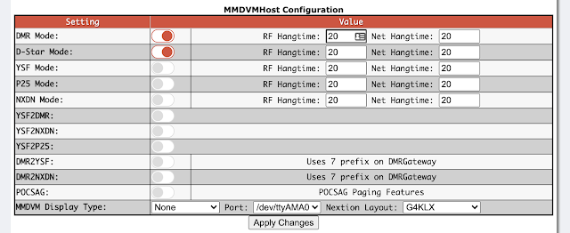
MMDVMHost Configuration:
- DMR Mode on; everything else off
- If you have an OLED display, it can be configured here
General Configuration:
- Set the Callsign, DMR ID, Lat/Long, Town, Country, etc, according to your own station. Obviously, mine are shown below - and you need to change these.
- URL conventionally should point to your QRZ.com page.
- Radio frequency can be your choice (within the bandplan, obviously). 438.8 MHz is a good choice for UK.
- Radio/Modem Type as shown below, i.e. MMDVM Hat for Pi on GPIO.
- Node Type should be "Private" in the UK (unless you are licensed for repeater operation).
- APRS can be off.
- Time Zone and Language according to your location and preference.
Under "DMR Configuration", select a suitable DMR Master. For the UK Phoenix network (also known as DMR+, and including DV Scotland), the recommended choice is "DMR+_IPSC2-DVSPh-F":
However, you can select any IPSC2 host. So if, for example, you want to connect via New Zealand there is nothing to stop you selecting "DMR+_IPSC2-NewZealand".
5. Code Plug
The easiest way to add the hotspot to the RT3S configuration is to create a new Zone in the Code Plug. As always when creating or editing a Code Plug, the steps are:
- Create Digital Contacts for each of the talkgroups required. Existing Digital Contacts can be reused, and you probably already did this in Part 2.
- Create Channels for each of the Digital Contacts. Because the Hotspot is on a different frequency from your repeater(s), new Channels are necessary.
- Assign the Channels to an existing or new Zone.
5.1 Digital Contacts
This was already covered in
Part 2, and the same Contacts can be reused.
I recommend creating the following (if they don't already exist), as Group Call entries:
- 1 - Worldwide calling
- 2 - Europe
- 9 - Local
- 13 - Worldwide English calling
- 80 - UK chat
- 81 - UK chat
- 82 - UK chat
- 83 - UK chat
- 84 - UK chat
- 113 - Worldwide English
- 119 - Worldwide
- 123 - Woldwide English
- 129 - Worldwide
- 235 - UK Calling
- 801 - Southeast region (substitute your own region and/or add other regions)
- 23526 - Hubnet
- 9990 - Echo test
- 900 - Disconnect (see Part 3a for details)
The part-built Digital Contact list looks like this:
5.2 Channel Information
For every Digital Contact from section 5.1, create a new Channel. Because the Hotspot is on a different frequency from your repeater(s), existing Channels cannot be reused.
Here is an example Channel configuration:
"Channel Name" can be according to your preference, but it is limited to 16 characters. I have used "Hot" - to indicate Hotspot; "TG1" - for Talkgroup 1; "WW Call" - as a reminder that this is the Worldwide Calling Talkgroup.
Power should be "Low" for a hotspot, to avoid overloading it.
RX and TX frequency will be the same for a simplex hotspot, and set the same as in the Pi-Star general config from Section 4.
"Admit Criteria" should be set to "Color Code", and the "Color Code" is 1.
"Contact Name" matches the appropriate Digital Contact entry from Section 5.1.
"Group List" and "Scan List" can be "None".
The "Repeater Slot" is always 2, regardless of the slot required on the Phoenix network. Don't worry; the Pi-Star will automatically translate to the correct Phoenix timeslot.
5.3 Zone Information
You can, of course, configure Zones to your personal preference. You might add the new Channels to an existing Zone. For simplicity, I prefer to have a separate Zone for my Hotspot.
Create a new Zone in the Zone Information part of the Code Plug, and name it "Hotspot". Add the new Channels to the Zone:
The choice of A or B is personal preference. I follow the Phoenix convention of putting international Talkgroups in A and local Talkgroups in B.
5.4 Button Definitions
Purely personal preference, but when working with multiple Zones I like to assign the up/down Zone function to a short press of the side buttons above and below the PTT:
6. Testing
Load the modified Code Plug to the RT3S (connect the USB cable, and Program/Write Data).
Check that the Dashboard looks correct:
- DMR enabled
- TX/RX frequency set
- DMR ID set to your ID
- DMR CC set to 1
- TS1 disabled, TS2 enabled
- DMR Master has connected to Phoenix F
Connect to the
Phoenix F dashboard and check that your Hotspot (listed by callsign) is appearing there.
Now try an Echo Test on 9990, followed by putting out a call on UK 235. You should see suitable activity on both the Pi-Star dashboard and the Phoenix F dashboard. Perhaps you'll even get a reply!
The next part in this series shows how to drop a dynamic talkgroup from the Hotspot.


Comments
Post a Comment