Constructing a simple dipole for 6m (50 MHz)
This was a fun little construction project, and very successful. The objective is a dipole for use on 6m, which I can deploy easily with my Vine Antennas Skypole Max, for temporary use on contests and FT8.
The dipole uses two sections of telescoping aluminium tube for each element. Although a single piece of tube (or rod) could be used, lengths of over 1m are much more expensive to buy, and also attract additional delivery charges. Constructing the antenna using 1m lengths is much more economical, and gives the possibility of adjusting the element length by sliding one tube inside the other... of which more later.
The construction method uses a central plastic box, which provides the following functions:
- mounting point for the two dipole elements
- contains a choke balun
- BNC termination point for the feeder
- method of attachment to the pole
Parts List
- 125 x 80 x 32 mm project box - Amazon
- 2 lengths 1m x 10mm aluminium tube - Amazon
- 2 lengths 1m x 8mm aluminium rod - Amazon - but what I actually received was aluminium tube (not a problem, but not what is shown in the Amazon link)
- 10mm U-bolts - Amazon
- Solder tags - Amazon
- RG174 coax - Amazon - cheapest to buy this 6m length terminated in SMA connectors, which can be reused
- FT140-43 ferrite toroid - Spectrum Communications eBay shop
- 20-32mm hoseclips - Screwfix
- 10-16mm hoseclips - Screwfix - bought but not needed (see below)
- 6mm nuts and washers - Screwfix
- short piece of 8mm plastic rod - see below
- nuts and bolts for hoseclips
- cable ties
- BNC socket
Construction


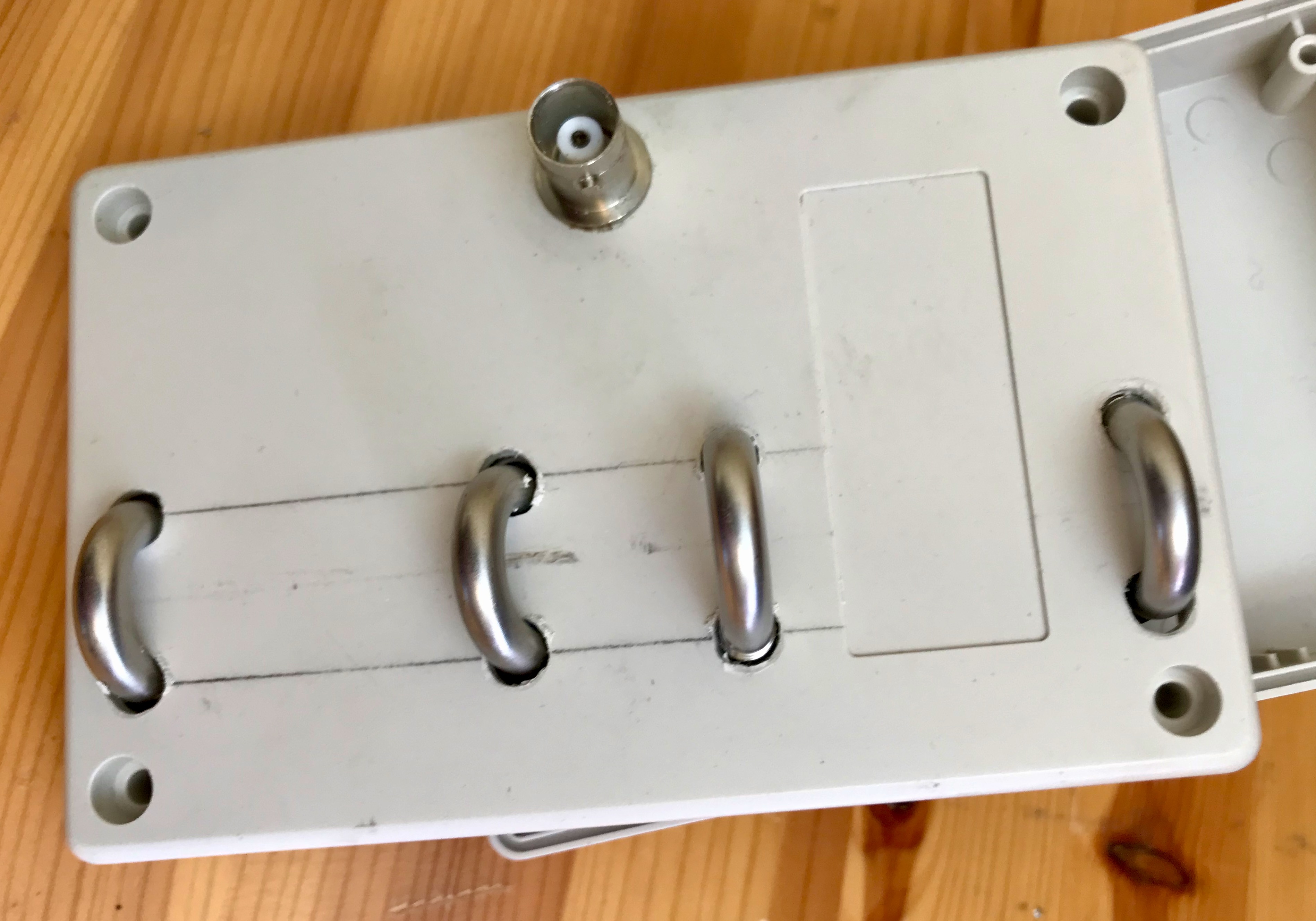
On the other half of the case, I drilled holes for four U-bolts to support the elements, and also a hole for the BNC socket. Note that the elements are entirely outside the box, and the electrical connection is via the U-bolts. The two inner U-bolts have solder tags attached on the inside of the case.


Adjustment and testing

measured freq / desired freq = adjustment factor
47.2 MHz / 50.2 MHz = 0.94
So the elements need to be shortened by a factor of 0.94:
starting length x adjustment factor = desired length
1500 mm x 0.94 = 1410 mm
The final step was to disassemble the elements, cut them down to 1410 mm, and reassemble.
The result is an antenna with low SWR across the 6m band, with a minimum of below 1.1 at 50.2 MHz. Testing on FT8 immediately gave me PSKreporter reports from Cornwall in one direction and Norway in the other... far in excess of anything I had achieved previously.
Success! Here is the finished item (alongside my HF MFJ mag loop):


Comments
Post a Comment