A self-adhesive slot antenna for 70 cm
Credits and Background
The inspiration for this antenna came from an excellent workshop led by Richard M0GET at a recent meeting of SEMARC. Additional ideas are from the Kindle book Slot Antennas for Ham Radio: The Forgotten Antenna by John Fortune W6NBC.
The aim of this design is a simple antenna that can be stuck onto an outside window, providing vertical polarisation primarily for access to the local repeater on 70cm (FM and DMR). An unusual property of slot antennas is that a horizontal slot provides vertical polarisation - so this makes a much easier and tidier installation than (say) an equivalent vertical wire dipole.
Construction Details
The materials needed are:
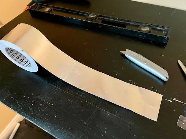
- Some self-adhesive, conductive tape. I used this 75mm tape from Screwfix, but really any copper or aluminium tape will work, and the width is not critical.
- A short piece of thin 50Ω coax, terminated with a suitable connector. I happened to find something suitable in my junk box: a short piece of RJ174 already fitted with an SMA connector.
- Two ring-type solder tags. Again, I happened to find these in my junk box.
- A self-adhesive cable clamp, to provide strain relief. Another junk box item.
 |
| 75mm Aluminium Tape |
Step 1:
Measure and cut 380mm length of tape. This dimension is not critical.
Step 2:
Cut a slot 310mm long and approximately 5mm wide in the centre of the tape. The length should be exact, but the width is not critical.
When cutting the slot, use a very sharp knife (preferably a new blade) and try to cut through just the aluminium layer and not the backing paper. Peel the aluminium off, leaving the backing paper in place. This makes the antenna much less likely to crinkle when it is attached to the window. Don't worry - this is actually much easier to do than it sounds!
A note on dimensions: I have given the exact dimensions here of my antenna which is tuned for 432 MHz and achieves a 1:1.1 SWR. If you prefer to do the final tuning yourself, then cut the slot longer. See below for tuning instructions.
 |
| Slot cut and foil removed, leaving backing paper in place |
Step 3:
Solder tags onto the end of the coax feeder. Bend the end of the tags by 90°.
 |
| Solder tags and feeder |
 |
| Attached and bent 90° |
Step 4:
Attach the tags to opposite sides of the slot, 70mm from one end of the slot. Use a square of the self-adhesive tape to secure each tag. This should be sufficient to provide good electrical connection (as well as mechanical attachment), but actually it isn't critical as there will be enough capacitance to provide an effective RF path.
A further piece of tape can be used to secure the end of the feeder. Note that the radiation pattern will be vertically polarised, so a horizontal run of coax should not upset the antenna.
 |
| Tags stuck down using tape |
 |
| Another view of the feed point |
 |
| Strain relief for the feeder |
Step 5:
Although it is tempting to just peel off the backing paper, a better approach is to only remove a strip around the edges of the antenna. This helps prevent crinkling when the antenna is attached. It also makes it easier to remove the antenna, should you ever need to!
So... turn the antenna over, and using a ruler as a guide, tear off strips of backing paper from all four edges.
 |
| Tearing off the backing paper |
 |
| Adhesive exposed around the perimeter of the antenna |
Step 6:
Carefully stick the antenna onto the window. Attach a longer feed line (using RG58 or similar) to the stub, and connect this to your radio. I have used a self-adhesive cable clip to provide support for the feeder.
In my case, the chosen window is double-glazed with clear glass. The metal window frame does not seem to cause a problem. Tinted windows with any kind of metallised coating are probably not a good idea. I can open the window to provide up to 90° of rotation!
The result should be a well-matched, vertically-polarised antenna.
 |
| Attached to the window |
 |
| Longer feeder attached, with supporting cable clip |
A note on tuning
I tuned this antenna and arrived at the final dimensions by building some prototypes and adjusting them using a nanoVNA. This is how I went about it.
- Start by cutting the slot too long. Perhaps 340mm.
- Attach the feed point too far from the short end. Perhaps 85mm.
- Connect a VNA, and measure the impedance. It will probably be higher than 50Ω. Now cut some small strips of aluminium foil, and use these one at a time to stick across the end of the slot to shorten it. Work on the short end first, monitoring the impedance. Each strip added will bring the feed point closer to the end of the slot, reducing the impedance. Try to get it somewhere close to 50Ω. Remember: impedance reduces (eventually to zero) by moving the feed point closer to the end of the slot.
- Now use the VNA to measure the resonant frequency of the antenna, which is probably too low. Patch the long end of the slot by adding strips of tape, monitoring the resonant frequency. Each shortening of the overall length should raise the resonant frequency, until you reach 432MHz, or whatever frequency you are aiming for.


Crystal clear and comprehensive writeup Russell, and great job on the build.
ReplyDelete